Residential Intercom Wiring Diagram
A residential IP intercom system is a modern and convenient way to communicate with visitors at the front door. It uses the internet protocol (IP) to connect to your home network, allowing you to answer the door from your smartphone or other device.
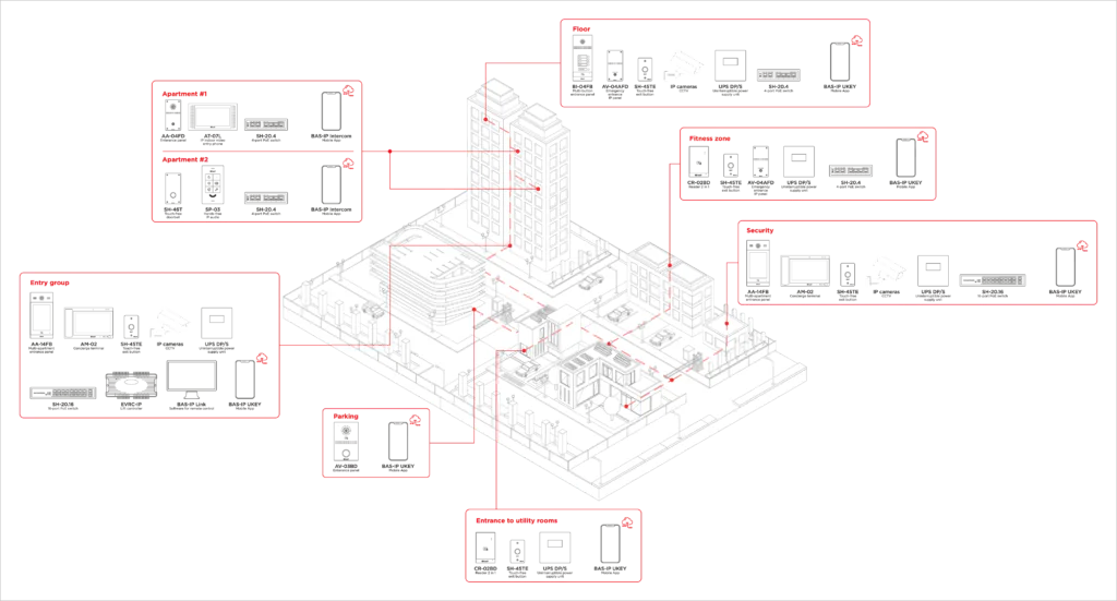
Residential intercom wiring diagram typically includes the following components:
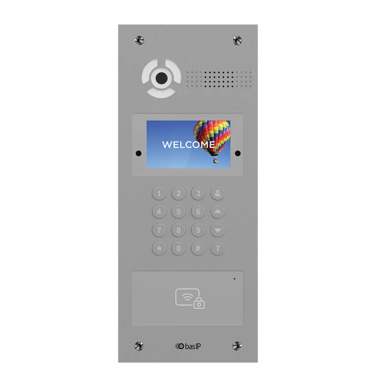
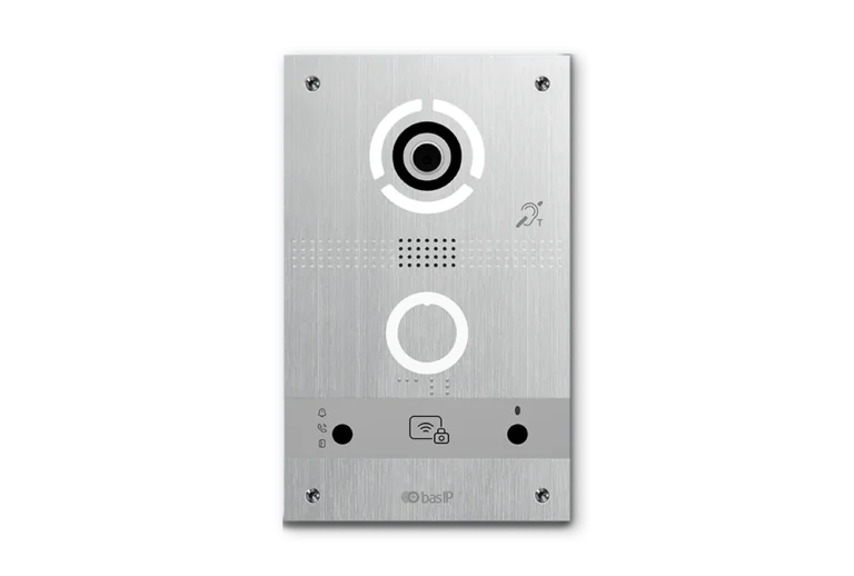
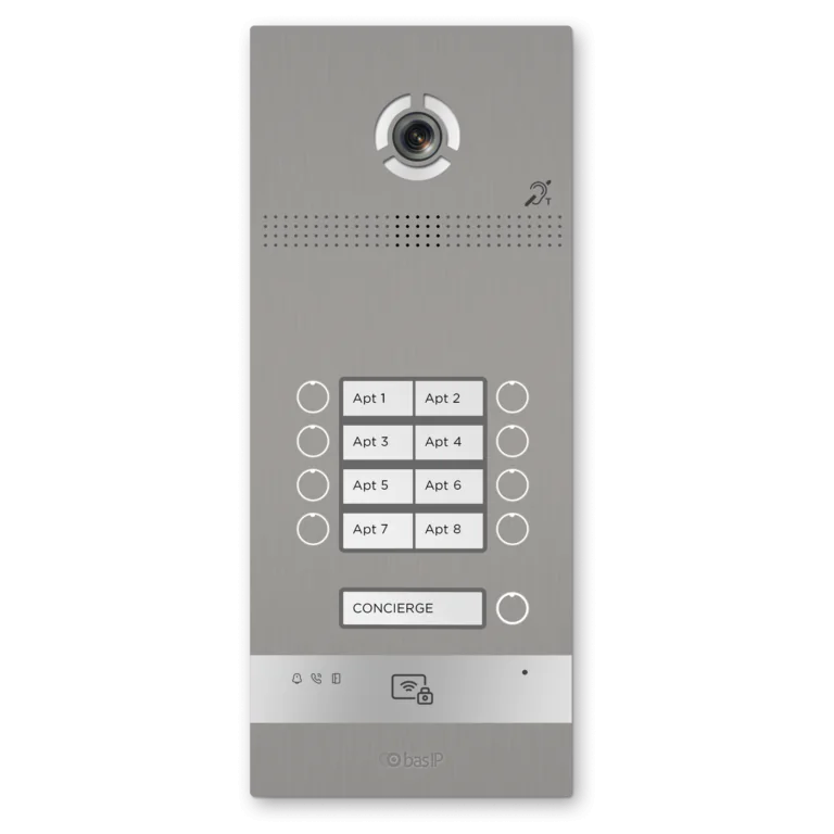
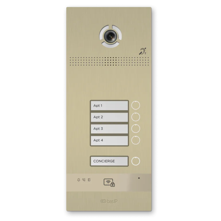
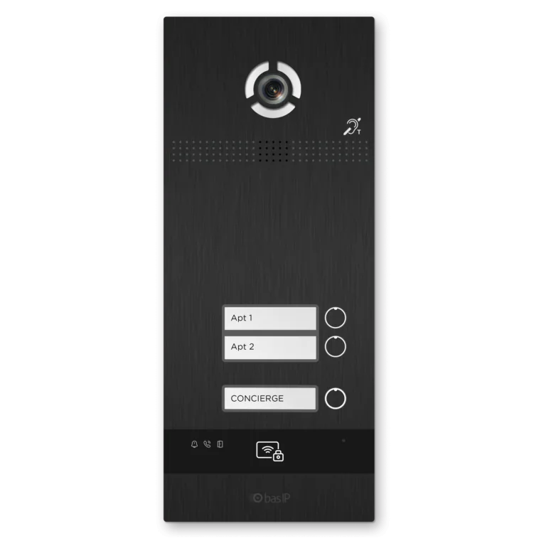
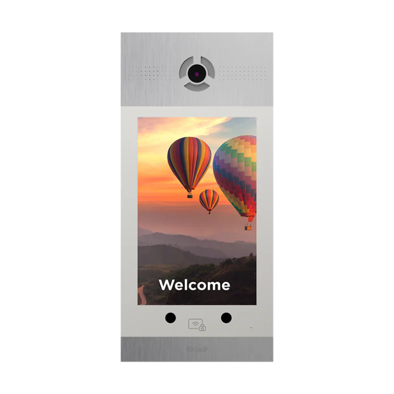
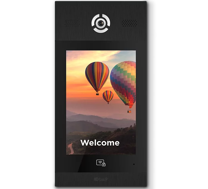
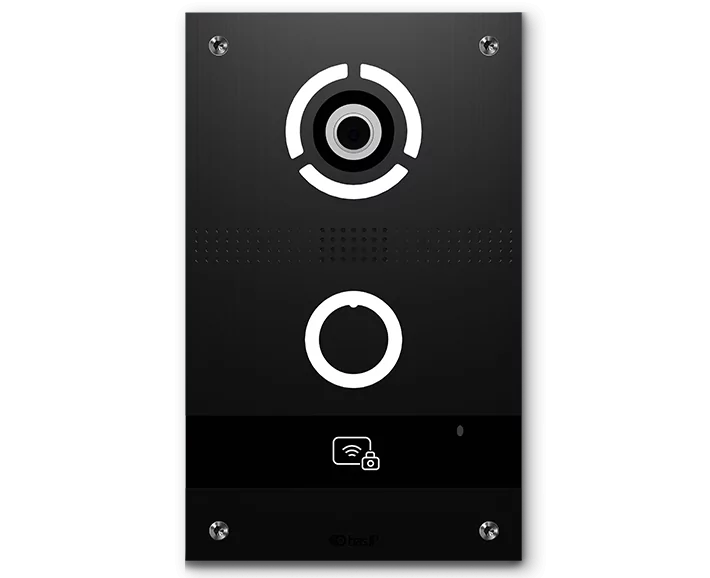
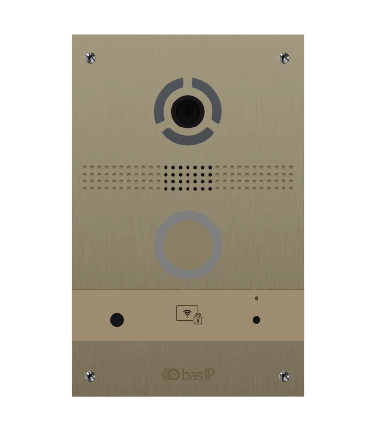
Door Entry Panel: This is the unit located at the front door, which includes a camera, microphone, speaker, and reader (as an option). The front door unit is usually wired to the network switch via an Ethernet cable. POE support.
POE Switch: The POE switch is used to connect all the components of the intercom system to the local network and give power to all IP intercom units.
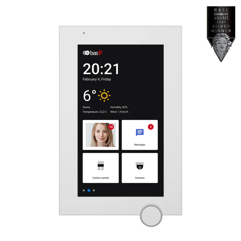
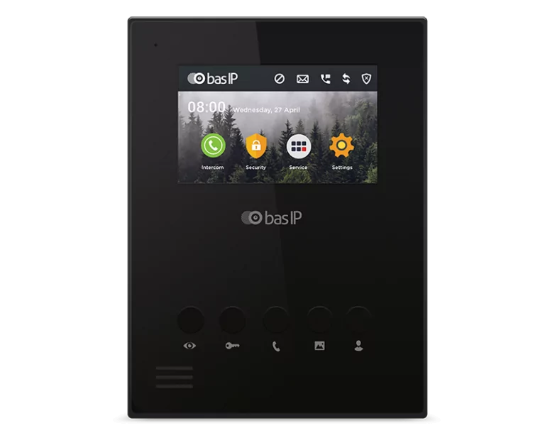
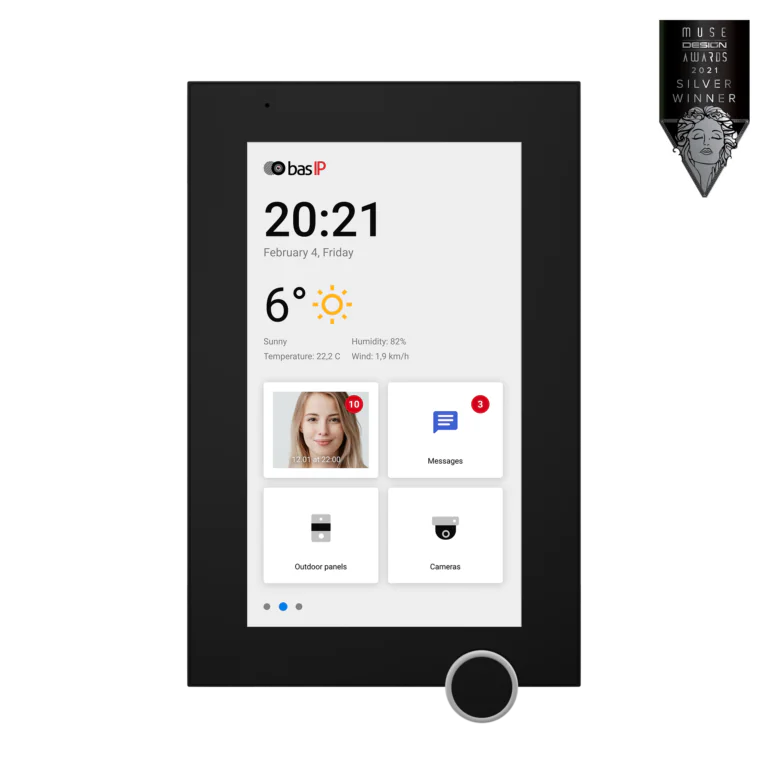
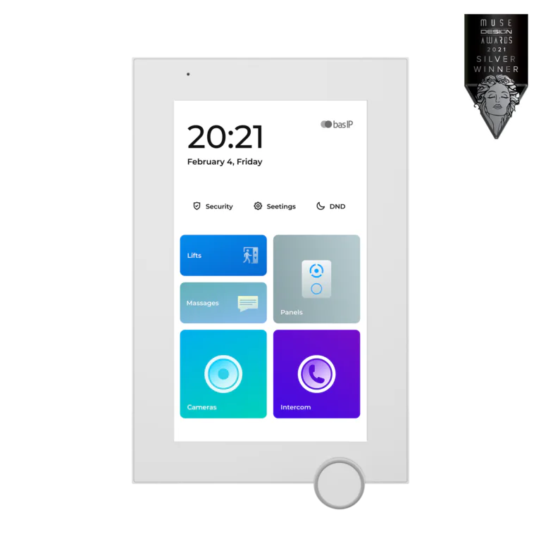
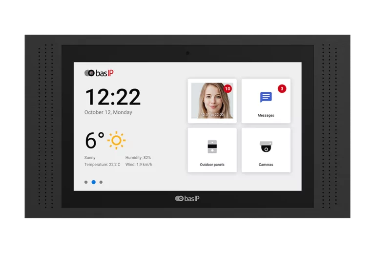
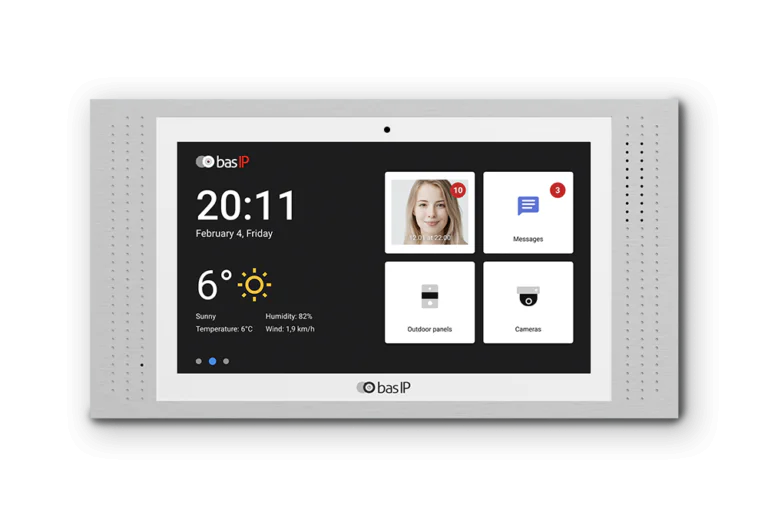
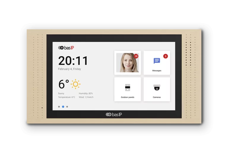
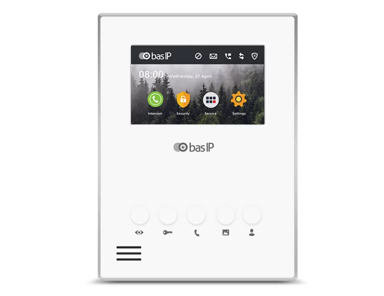
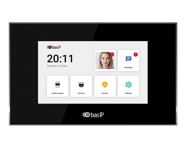
Indoor Phone: The indoor phone is typically a monitor (indoor video phone) or handset (indoor audio phone). It is used to receive calls from the door entry panel and communicate with visitors.
The wiring diagram for a residential intercom system is relatively simple.
