Cat 5 Cable Wiring Diagram, Cable Order
In today’s world, the internet is as essential as the air we breathe. We rely on it for everything, from catching up on the latest news to streaming our favorite movies. But have you ever wondered how this magic works? Well, a big part of the answer lies in tiny lines of wires known as Cat 5 cables.
Indeed, we delve into such details because the Cat 5 cable is truly the lifeblood of the BAS-IP CAT5 intercom system. This system, renowned for its seamless communication abilities and high-quality video intercom features, relies heavily on the Cat 5 cable for its operation. The cable, when wired correctly following the T568A or T568B order, ensures swift and steady data transmission – a factor that is crucial for the performance of the intercom system.
The Cat 5 Cable Diagram – The Heart of the Internet
Understanding the cat 5 cable diagram is like cracking the code to our digital world. These humble bundles of wires, neatly organized and color-coded, carry vast amounts of information from one point to another.
The Basics of a Cat 5 Cable
Before we dive deep into the cat 5 cable diagram, it’s essential to understand what a Cat 5 cable is. It’s a type of twisted pair cable, typically used for Ethernet and telecommunications. Made up of four pairs of tiny copper wires, it’s capable of transmitting data at speeds up to 100 Mbps.
Decoding the Cat 5 Cable Diagram
The cat 5 cable diagram is like a roadmap, showing how these eight wires are arranged. There are two standards – T568A and T568B. The only difference between them is the order of the color-coded wires.
Cat 5 Wiring A or B: The Colors of Connection
Cracking the color code is key to understanding the cat 5 cable diagram. Each pair of wires follows a specific pattern, which enables the correct transmission of data.
The T568A Standard
In the T568A standard, the pairs are arranged as follows:
- Green and white-green
- Orange and white-orange
- Blue and white-blue
- Brown and white-brown
The T568B Standard
The T568B standard is a tad different, with the pairs arranged like this:
- Orange and white-orange
- Green and white-green
- Blue and white-blue
- Brown and white-brown
When to Use Which Standard?
Choosing between T568A and T568B depends on your specific needs. While both are equally capable, the T568B is more commonly used in commercial installations, while the T568A is often seen in residential setups.
Cat5 / RJ45 Cable Order
| Pin | T568A Color | T568B Color | Function |
|---|---|---|---|
| 1 | White/Green | White/Orange | Transmit+ (TX+) |
| 2 | Green | Orange | Transmit- (TX-) |
| 3 | White/Orange | White/Green | Receive+ (RX+) |
| 4 | Blue | Blue | Not used |
| 5 | White/Blue | White/Blue | Not used |
| 6 | Orange | Green | Receive- (RX-) |
| 7 | White/Brown | White/Brown | Not used |
| 8 | Brown | Brown | Not used |
In an Ethernet connection, pins 1 & 2 are used for transmitting data, and pins 3 & 6 are used for receiving data. Pins 4, 5, 7, and 8 are not used in a 10BASE-T or 100BASE-TX Ethernet connection, but might be used in other types of networks or in power over Ethernet (PoE) applications.
Please remember when viewing the RJ45 connector (clip facing down, copper contacts facing up), the pin order is from left to right. Both T568A and T568B standards are interchangeable, so choosing between them often depends on personal preference or regional standards.
Cat 5 Cable Diagram: Straight-Through Wiring vs Crossover Wiring
When it comes to Ethernet cables, there are two main types of wiring configurations: straight-through and crossover. The choice between these two depends on the devices you’re trying to connect.
Straight-Through Wiring

In straight-through wiring, both cabel ends follow the same wiring order. This means that Pin 1 at one end of the cable connects to Pin 1 at the other end, Pin 2 connects to Pin 2, and so forth. This is the standard cable configuration for connecting devices that use different types of Ethernet ports.
For instance, you’d use a straight-through cable to connect:
- A computer to a switch or hub
- A router to a switch or hub
- A modem to a router
Crossover Wiring
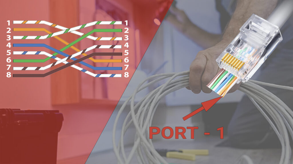
In crossover wiring, the order of the wires at one end of the cable is reversed at the other end. This means that the Transmit pins (1 and 2) at one end are connected to the Receive pins (3 and 6) at the other end, and vice versa.
Crossover cables are used to connect devices that use the same type of Ethernet port. They essentially “cross over” the Transmit and Receive lines, allowing the two devices to communicate directly without the need for a switch or hub.
Typically, you’d use a crossover cable to connect:
- A computer to a computer
- A switch to a switch
- A router to a router
It’s worth noting that many modern devices can automatically detect the type of cable and adjust their wiring configuration accordingly. This feature, known as Auto-MDIX, has made crossover cables less necessary in recent years. However, it’s still important to understand the difference between straight-through and crossover wiring, especially when working with older equipment.
Cat 5 Wiring Diagram Pdf
Making Connections: Wiring Your Own Cat 5 Cable
Armed with the knowledge of the cat 5 cable diagram, you can now wire your own cat 5 cable.
Tools You’ll Need
- Wire cutters
- RJ45 connectors
- Crimping tool
Steps to Follow
- Cut the cable to the desired length.
- Strip the outer casing to reveal the four pairs of wires.
- Arrange the wires according to the chosen standard.
- Insert the wires into the RJ45 connector.
- Use the crimping tool to secure the connector.
Common Misconceptions About Cat 5 Cables
Like any complex technology, there are many myths surrounding Cat 5 cables. Let’s debunk a few of them.
Myth 1: Cat 5 and Cat 5e Cables Are the Same
While they may seem identical, Cat 5e cables are an enhanced version of Cat 5 cables. They can handle higher data rates and are more resistant to interference.
Myth 2: The More Twists, the Better
While it’s true that twisting reduces interference, too many twists can degrade the signal quality. It’s a delicate balance that manufacturers strive to achieve.
Myth 3: Any Connector Will Work
The type of connector used can significantly affect the quality of your connection. Always ensure to use RJ45 connectors for Cat 5 cables.
Cat 5 Wiring Troubleshooting
When wiring an Ethernet cable, like a Cat 5, it’s crucial to follow the right wiring diagram. If you wire an Ethernet cable wrong, it might lead to several issues. Let’s explore some of them:
No Connection
The most common consequence of incorrectly wiring an Ethernet cable is no network connection. If the wires within the cable are not arranged and connected according to the cat 5 cable diagram, your devices may fail to communicate with each other.
Intermittent Connection
In some cases, you might end up with an unstable, intermittent connection. This could manifest as random disconnections, slow data transfer rates, or even packet loss during data transmission.
Cross-Talk and Interference
Cross-talk occurs when signals from one pair of wires interfere with signals from another. This can degrade the quality of your connection and may even result in data loss. Proper wiring of Ethernet cables following the cat 5 cable diagram reduces cross-talk and interference.
Damage to Network Devices
In extreme cases, incorrectly wiring an Ethernet cable could potentially damage your network devices. This scenario is rare, but it can occur if the miswiring results in a short circuit.
Frequently Asked Questions
Conclusion
The cat 5 cable diagram is more than just a bunch of colored wires. It’s the blueprint that keeps our digital world humming. So the next time you’re streaming your favorite show or video chatting with friends, spare a thought for these humble cables and the intricate cat 5 cable diagram that makes it all possible.